|
We consider now the interference of two
delayed versions of a lightwave that propagated in two different dielectric
materials. The first lightwave traveled a distance z1 in a dielectric
material characterized by the refractive index function n1(n), while the
second wave propagated a distance z2 in a dielectric material with n2(n). We assume
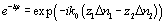
that both materials are not dispersive (Dn0 = 0). The two electric field amplitudes Ei
(i = 1,2) at the interference location are given by


|
(4-23) |
where ti represent the time needed for the wave to travel the distance zi
(the travel distance in vacuum is ngzi) and
i = 1, 2. The intensity signal obtained when the electrical
fields E1 and E2 are superposed is found by noting that
the factors exp(-ik0z1,2Dn1,2) are
frequency independent

|
(4-24) |
The first difference observed by
comparison with propagation in vacuum (4-10) is that delay times are
related to the group velocity and not to the vacuum light speed (for a physical
distance d in a dielectric material, the vacuum delay time corresponds to a
travel distance of d/ng). The second difference is the inner
exponential factor
 .
This phase factor changes the position of the constructive and destructive
interference but not the interference amplitude. It is interesting to calculate
the typical behavior of j for propagation in fibers around l = 1300 nm
where the dispersion is null (typical value of Dn = -0.014)
.
This phase factor changes the position of the constructive and destructive
interference but not the interference amplitude. It is interesting to calculate
the typical behavior of j for propagation in fibers around l = 1300 nm
where the dispersion is null (typical value of Dn = -0.014)

|
(4-25) |
For every step of distance
z = 100 mm a complete scan of 2p is performed (an interference period has been
added).
This effect is not fundamental for
all-fiber interferometers operating at 1300 nm as the delay time is
performed by a moving mirror in air (Dnair = 0). Nevertheless,
a fixed phase factor exists due to a material difference between the reference
and test arms as can be seen in Fig. 4-5 (simplified view of Fig. 4-2a).
The relevant part is the optical fiber section between the positions Pte
and Pt in the test arm, where Pte and Pfe
(fiber end position in the reference arm) have the same distance from the
coupler. The typical length of this section is several centimeters and then the
constant phase factor is not easily obtained.

Fig. 4-5 Simplified OLCR set-up
|